Serial communications
Theory
How do we communicate data between computers, or between
peripherals and the CPU? We've already talked about one way to
communicate data: using a bus. The thing is, a bus is expensive
(it needs a wire for every bit, plus wires for control information).
It turns out that we can trade some money for speed, and cram all the
bits down a single wire. This is the idea behind serial communication.
Parallel-serial conversion
Let's suppose we have some data we want to pass down the line. To do
this, we need a "shift register" at each end. A shift register is a
register that we can shift data through, one bit at a time, bringing
data in one end and putting it out the other. Normally, you can also
read or write all of the bits of a shift register at the same time.
So the idea is that we can put a whole byte into the shift register
all at once, and then ship it down the wire one bit at a time.
To use shift registers in serial communication, we need two of them.
At the transmitter end, we need to be able to load up all the data
bits in parallel, and then shift them out one bit at a time. At the
receiver end, we need to be able to shift the data in one bit at a
time, and then read the whole eight bits at once.
Bits per Second and Baud Rate
Now, we start to get into the details. First, how long (in time) is a
bit? If the transmitter and the receiver don't agree, the receiver
will get the wrong data. There are a bunch of standard bit-per-second
speeds that are used; these are all multiples of 300 bps for
historical reasons (note -- the new 56K modems seem to be an exception
to this). Also for historical reasons, we frequently say baud (named
after Baudot) when we mean bps. It turns out that these don't mean
quite the same thing -- baud means the actual number of voltage
transitions possible; modems use some pretty fancy signal processing
techniques to encode more bits/second than the actual baud rate. Next
question: how many bits are in a character? The original baudot code
was a five bit code (I have no idea how they got the whole alphabet
plus numbers in there!); for a very long time we normally saw a seven
bit character; today we normally see an eight bit character.
The next problem is making sure the data is sent correctly. There are
two subproblems here: getting it to work at all, and getting it to
work in the presence of noise.
Start Bit
The transmitter is not going to send data continuously. You've seen
this in doing downloads, and in running hexmon: there's normally more
time spent between sending characters, than actually sending them. When
you're not sending data, the line is held at a steady value of "1."
So, how do you tell when a data character is coming? Suppose we see a
binary sequence 11111111000011111. If we're using a
seven-bit ASCII character, this could be 1110000
('p'), 1100001 ('a'),
1000011 ('C'), or 0000111
(BEL). It could even be two characters, with some of the
0's in each one! These possibilities are 1111110 0001111
('~/', 1111100 0011111 ('|US')
or 1111000 0111111 ('x?'). How can we tell
the difference?
What we'll do is put a 0 bit in front of every character,
to tell it that a character is coming (the 0 isn't be
part of the data, it's in front of the data). We call this a "start
bit;" it marks the start of a data character.
Stop Bit(s)
Now, suppose we get some noise on the line. We can end up thinking a
data bit is the start bit, and read a character of nonsense. There are a
couple of things we can do about this. The first one is to use a stop
bit: we follow each data character with some fixed number of
1's. This means the receiver does the following to try to read a
character:
- Wait until it sees a 0.
- Read the bits following the 0.
- Make sure the character is followed by the right number of 1's.
If it isn't, we had an error.
Parity
Notice that this will miss a lot of errors, especially if there's a
lot of time between characters. If the noise ended halfway through a
character, we'll see everything after the next 0 in the character as
data, and then see the 1's that go between characters as more data.
We can do a little better than this by adding another bit, called a
parity bit. On the transmitter end, we'll take a look at a character
to be sent and ask, "are there an even or an odd number of 1's in
this character?" Then, we'll inject an extra bit after the character
(but before the stop bit) to force the number of 1's to be either even
or odd (our choice). So if we're going to send out "odd parity," we
make sure that the character+parity bit always contains an odd number
of 1's. If we're going to send out even parity, we'll make sure it's
even. There are five parity functions:
- No parity. Don't send out a parity bit at all.
- 0 parity. Make the parity bit always 0.
- 1 parity. Make the parity bit always 1.
- Even parity. Use the parity bit to make sure the parity of the
character+bit is even.
- Odd parity. Use the parity bit to make sure the parity of the
character+bit is odd.
A Few Last Notes on Parity, Character Length, and Stop Bits
Programming RS-232 ports would be hard enough if you actually had to
get the configuration right for it to work. Amazingly, there are a
bunch of ways you can come up with configurations that don't agree,
but which work - or even worse, that almost work.
For instance, you might have one end set to 8 bits of data, 1 parity,
and 1 stop bit, while the other end is set to 8 bits of data, no
parity, and two stop bits. It'll work!
Or, you could have one end set to 7 bits of data, 0 parity, and 1 stop
bit, with the other end set to 8 bits of data and 1 stop bit. This
will work as long as you only send ASCII characters; as soon as the
end supporting 8 bits of data sends a character with the most
significant bit set the other end will report a parity error. This
will manifest itself as something like successfully running a text
editor over the wire (for hours at a time!), but failing very quickly
when you try to download a file.
Real Life
At one time, the capabilities described for serial ports were all
needed to make sure data was not lost. People tended to work at dumb
computer terminals, which communicated over relatively long distances
to central computers. Where I went to school, they even economized by
using only two wires to connect the terminals to the department's
computer: one wire for data in each direction. They relied on the
building ground to provide a signal ground! This worked surprisingly
well for a long time; we just saw noise on the line whenever the air
conditioner started up or something. As time went on we kept adding
more terminals and computers; then one day the ground plane got noisy
enough that the whole scheme basically quit working completely, which
required an emergency rewiring of the whole building.
Networks
This idea of putting extra "stuff" around the data you're actually
interested in is called putting the data in a frame, and is a very
standard technique in networking.
For most networking, the frame is quite a bit more complicated than
this, because additional routing information is also required.
A data packet is typically sent out with information that encodes
things like what computer the packet started at, what computer it is
supposed to go to, what process on the destination computer it is
intended for, and so forth. We already know all this stuff in our
application, so we can just send a bunch of bytes.
An example of a more complicated data frame is how data is sent on an
ethernet. An Ethernet packet contains:
- A 62 bit preamble (consisting of alternating 1's and 0's) and
two bit start of frame delimiter (this is two 1's). This
is an extension of the start bit, which serves to let all the
receivers on the wire know that a packet has started.
On an oscilloscope, this preamble is a 5MHz square wave (for 10 Mbit
ethernet). This gives the receiver a good long chance to sync
up its phase-locked-loop oscillator to the signal.
- A 48 bit source and 48 bit destination field. It turns out that
every NIC card ever built has a "unique" 48 bit ID number, called
its MAC (Media Access Control) address (this is frequently
called its hardware address). So we are able to send a packet
from a sender to a receiver on an ethernet segment (if the
sender and receiver are on different segments, or have a
telephone link or something between them, things get more
complicated in a hurry). (I say "unique" because, while the
MAC address was originally supposed to be unique, it really
isn't any more, for two reasons. First, blocks of MAC addresses
have been assigned to various vendors; some of them have run out
of addresses and recycled them. Second, most modern NICs can
have the MAC address set by software. Still, it doesn't matter
much as long as all the NICs on a given ethernet segment have
unique MAC addreses)
- A 16 bit field encoding the type of the packet and its length.
For instance, a TCP/IP packet will have a value of 0x80 0x00 in
this field.
- The actual data, which will be between 46 and 1500 bits.
- A 16 bit CRC (Cyclic Redundency Check) field, which is used to
check that the data was sent correctly. This is an extension o
the parity bit described before.
Practice
HC11 Serial Capabilities
The HC11 is capable of sending and receiving data at a wide variety of
speeds from 75 to 125,000 bps (with the clock rate we're using). It
supports one start bit, one stop bit, and eight or nine data bits
(notice that we can play some games to "fake" other parameters: we
can set it for nine data bits, calculate the parity by hand, and put
it in the ninth bit, for example). It can deliver interrupts on a
variety of conditions (which we'll describe in a minute).
A very nice feature of the SCI is that it provides some limited
buffering, which makes it easier to keep the transmitter line
full at all times, and gives some latitude in receiving. Here's a
conceptual picture of the SCI port:
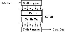
The "Data In" and "Data Out" lines are the actual serial IO wires
going in to and out of the chip.
On the input side, bits are read into a "shift register," one bit at a
time. When all the bits for a character have come in, it's moved into
the input buffer and is ready to be read. A more complete diagram,
showing things like the start and stop bits, is in the reference
manual as figures 9-1 and 9-2 (pages 320 and 322).
On the output side, the programmer writes a character to the output
buffer. The character is transferred to another shift register, and
sent out one bit at a time.
An odd thing about this diagram is the way
I've represented the SCDR (serial communication data register). The
idea here is that it's really two separate registers; when you read
it (by reading address $102f), you read the input
buffer. When you write to it (by writing to the same address, you
write to the output buffer. This seems really weird, but isn't at all
uncommon.
Configuration
Configuring the port requires setting the speed, defining the
character format, and enabling interrupts on desired conditions.
Looking at these in turn:
BAUD register
The BAUD register (at $102b) determines the speed the SCI
is running. The SCP1-0 and SCR2-0 bits select the rate (in
conjunction with the system clock speed). The other bits in the baud
register are not used. Table 9-1 in the reference manual gives a
table showing the various maximum baud rates possible depending on the
setting of these BAUD register bits; all we really care about in this
class is that setting them to 11 lets us get 9600 bps. Likewise,
table 9-2 (page 329) gives the actual baud rates obtained by combining
SCP1-SCP0 and SCR2-SCR0; again, what we care about here is that
setting SCR2-SCR0 to 000 will give us 9600 bps.
SCCR1 and SCCR2
The only important bit in SCCR1 ($102c) is the M bit (bit 4),
which selects 8 or 9 bit mode. The other bits are used when the
serial port is being used to implement a network, with a single wire
connecting a bunch of ports on a serial bus.
SCCR2 ($102d) is used to enable and disable virtually the
whole subsystem... transmitter, receiver, interrupts, etc. etc. The
bits are:
- TIE (bit 7)
- Transmit Interrupt Enable. When set to 1, the SCI will request
an interrupt when it's possible to write to the output buffer
without losing any characters.
- TCIE (bit 6)
- Transmit Interrupt Complete Interrupt Enable. When set to 1,
the SCI will request an interrupt when we're completely done
sending data. This is important if we're going to change the
speed, so we don't do something like try to change the speed
halfway through sending a character.
- RIE (bit 5)
- Receive Interrupt Enable. When set to 1, the SCI will request
an interrupt when new data has arrived for us to read.
- ILIE (bit 4)
- Idle Line Interrupt Enable. When set to 1, the SCI will request
an interrupt when the serial line is quiescent. Again, we only
want to change speeds when there is nothing on the line.
- TE (bit 3)
- Transmit Enable. Turns on the transmitter, so we can send data.
- RE (bit 2)
- Recieve Enable. Turns on the receiver, so we can receive data.
We don't really care about bits 1 and 0. Bit 1 is a "receiver wakeup
bit"; it's possible to set the receiver in a sleeping state and have
it wake up automatically. Bit 0 sends a "break" character; that's
implementing by sending enough 0's in a row on the line to guarantee
that the other side will get a framing error (what that means will be
described in a minute).
SCSR
The SCI Status Register ($102e) is used to report the
current state of the serial interface. This includes both data
presence/absence and error conditions. This register contains:
- TDRE (bit 7)
- Transmit Data Register Empty. This means the output buffer in
the figure is empty, so it's safe to feed a new character to the
system. If you put characters in before the port is ready, they
overwrite the characters already in the buffer and characters
are lost.
- TC (bit 6)
- This says the output buffer, and the output shift register, are
both empty. The reference manual talks in terms of using this
condition to see when a modem can be disabled; you would also
use it to see when you can safely change the transmission speed.
- RDRF (bit 5)
- This says the input buffer has data in it, and you can read the
data. If you just blindly read a lot of data without checking
this, you'll get the same character over and over again.
- IDLE (bit 4)
- This says the serial line is quiescent (no data is being sent on
it). Just in case we wanted to do something exotic like have
multiple transmitters and receivers on a single wire or
something.
- OR (bit 3)
- Overrun: oops. We didn't get around to reading a character
that had come in, and a second one came in while we were
waiting. The second character has been lost.
- NF (bit 2)
- Noise Flag: oops. The receive line is so noisy we can't trust
the data we got.
- FE (bit 1)
- Framing Error: oops. When we were done reading the character,
we got a 0 instead of our expected 1 for a stop bit.
One important thing to mention is that to clear these flags, you need
to read the SCSR, and then either read or write the SCDR as
appropriate (read it to clear the receiver-related flags, write it to
clear the transmitter-related flags).
SCDR
The SCI Data Register ($102f) is used to send/receive
data. It is actually two registers, which share a single address.
When you write to the register, you write to the transmiter UART.
When you read from it, you read from the receiver UART.