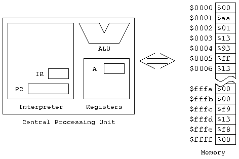
From our perspective in today's lecture, a computer has two important components: some memory and a CPU (this quite deliberately leaves out the whole input/output system, which we'll be dealing with extensively later. But it isn't important today).
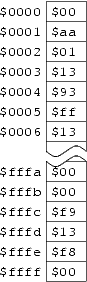
The memory is just that: it remembers things. You can put numbers into it, and you can take numbers out of it. The memory is organized so that every location has an address: so we have memory location 0, location 1, location 2, location 3, and so forth. You can think of it like an array; you can assign values to locations in the array, and get values out of locations in the array. Here's a figure showing the memory:
If you've come across hexadecimal arithmetic before, you've already
noticed that I've written the numbers in the memory as hexadecimal.
The $ in front of each one is how we will tell the
assembler that we want to use a hexadecimal number.
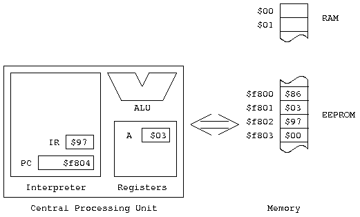
The Central Processing Unit is the part of the computer that does all the work. The main things it contains are:
We need to have memory actually in the CPU because getting it from "memory" takes too long (one of the major determiners of how powerful a computer is, is how many registers it has in the CPU, and how much can be transferred at a time between memory and the CPU); one of the most effective ways to make a program run faster is to make sure you have the most-used data present in the CPU at all times.
We'll be introducing the registers a few at a time, as needed. For today, we need the Program Counter register, and the A Accumulator. The PC always contains the address of the next instruction to be executed. A is a register where we "accumulate" results.So, here's a picture of the computer as we're looking at it today.
Let's take a look at a fragment of code in memory (this fragment is taken from a program you can find at http://www.cs.nmsu.edu/~pfeiffer/classes/273/notes/inst-execution.lst. Suppose we have
$f800:  $86
$f801:  $24
$f802:  $8B
$f803:  $12
Also, let's suppose that before we start, the PC contains
$f800. So here's what things look like before we start:
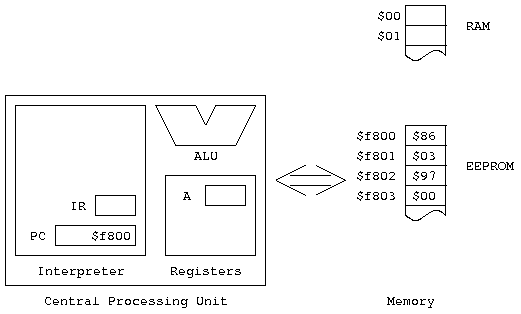
(of course, the IR and Accumulator A actually contain something. We just don't know what, and their initial contents won't be relevant to the example)
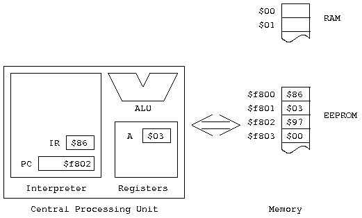
$f800, getting the value
$86 back. This is the instruction fetch,
and the number we just read from memory is called the instruction's
opcode (that's short for "operation code").
$86 means. To do this, we need to
turn to the Reference Guide, Page 8.
We look in column 8, row 6 (since those are the two digits in the
opcode). When we do this, we find a large box in the table, marked
LDA. That's the instructions name, which is short for
Load Accumulator. Notice that all of
the columns from $8 through $f, and row
$6, are Load Accumulator (LDA) instructions.
We can also find more information here: we also find that all of
the columns from $8 through $b, regardless
of row, are headed by ACCA. This tells us that all
of these instructions (including the one we're interested in) affect
Accumulator A. Finally, column $8 itself is headed by
IMM. This tells us that we're using immediate
addressing.
Putting all this information together, we're executing a Load Accumulator instruction, using Accumulator A, and Immediate Addressing. This figuring out what the instruction is, is called the instruction decode. Now we can turn to the Reference Manual to find out what it really does, and simulate it.
LDA instruction appears
on page 551.
This gives a complete specification of the instruction: first,
Operation tells us what it does — with a little help from
the nomenclature guide on pages 488 and 489, we see that the contents
of a memory location are copied into either Accumulator A or
Accumulator B. The Description: says the same thing, in
something more like English. We'll ignore the Condition Codes
for the moment, and turn to the tables at the bottom, where we see
that LDAA (IMM) performs the following steps:
$86. Of course, we already knew that; it's
how we started! Something that's implicit here is that every
time we read from the address pointed to by the PC, the PC is
incremented. So now it contains $f801.
ii means) from
OP + 1 — in other words, the
address the PC is now pointing to. After we've read it, we
increment the PC again, so it now contains $f802.
From the definition of the operation of the instruction, we know
that the value read in the second cycle is loaded into the A
Accumulator. The result is that
Acc A = $24.
All this stuff after the instruction decode is instruction execution.
Here's what things look like now:
Now we're ready to go to the second instruction.
$f802, getting an opcode of $8b this time.
$f803.
ADD, using accumulator A and
immediate addressing.
ADDA.
A + M => A,
is a more formal description of the instruction. For some
of the other instructions, this is a bit more illuminating.
A IMM (this is the same accumulator and
addressing mode as in the first example).
$8b. Of course, we already knew that.
ii.
The nomenclature table for the reference guide is on page 20;
once again, we see that ii means one byte of
immediate data.
$12 from$f803 and add it to the
previous contents of accumulator A. This gives us a new value
of $36 in the accumulator, and leaves the PC
pointing at $f804.So here's what things look like now:
At this point, the HC11 would proceed to read whatever is at
address $f804, and process it just like the
previous two instructions. But I haven't defined any
instructions to follow the two we've looked at, so the example
ends here!