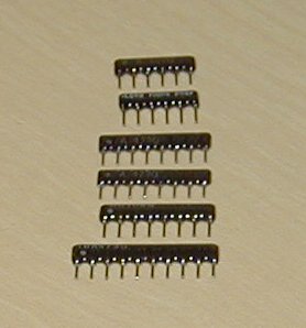
Resistor packs. The "E" and "V" markings don't necessarily appear. Note that a polarized (common ground type) resistor pack with n resistors will have n+1 leads; a non-polarized (isolated terminal type) resistor pack with n resistors will have 2n leads. The only ones you can't simply distinguish by the number of leads are RP1 and RP3; you'll need to use an ohmeter to be sure.
Remember that the polarized packs need to be installed facing the right direction; the non-polarized ones don't matter.
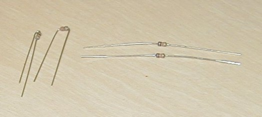
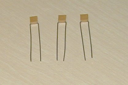
Single resistors. Be sure to identify them by color code. Bend the leads so they'll fit the holes properly; there are two examples in the picture.
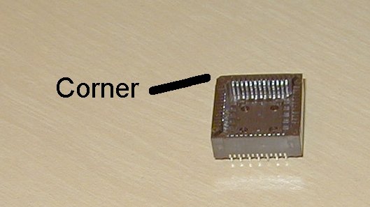
IC sockets. On the 14-pin socket, notice the notch.
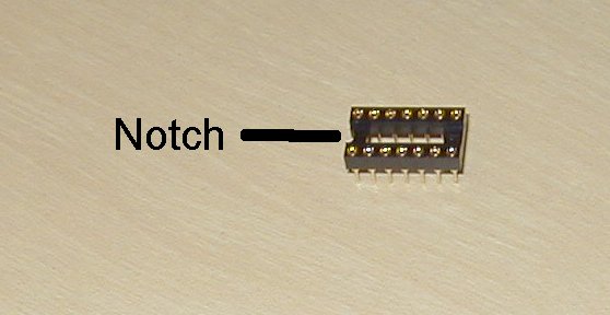
On the 52-pin, be sure you identify the "diagonal" corner: if you get this socket on wrong, it'll be really hard to put in the CPU!
Non-polarized capacitors
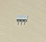
Ceramic Resonator. It looks a lot more "white" than "blue" to me.
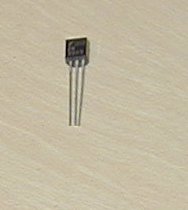
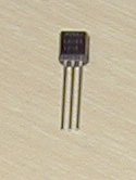
Transistor. This is really hard to distinguish from the voltage regulator (step 13). Be sure it says 2N3905!
LEDs. LED1-LED5 on the top row, LED6-LED10 on the bottom row. Notice the slight difference in lead lengths; the short lead goes in the shaded (white) side of the part location.

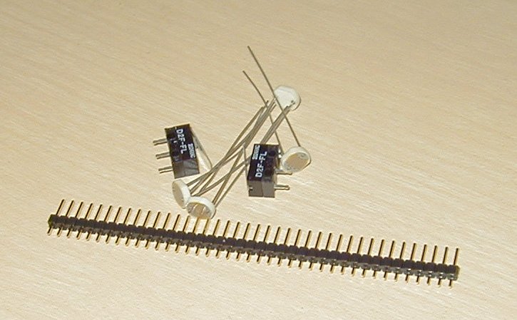
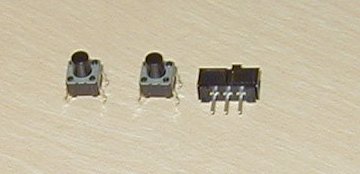
Switches. Two pushbutton switches, one small slide switch (the large slide switch will go elsewhere).
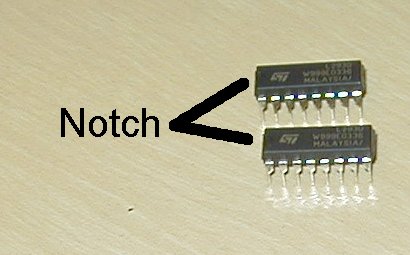
Motor controllers (direct-mount integrated circuits). Don't confuse them with the inverter, which will go in a socket! They are (1) identical, and (2) say "L293D" on them. Also, the notch in the end is nearly invisible in the picture, but is there and is important!
Power connector: we're not using it. Instead, follow the directions to install the 9volt battery connector, the diode, and the power switch.
No 9v connector at home to take a picture of...
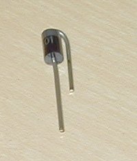
Power Diode
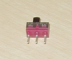
Power Switch
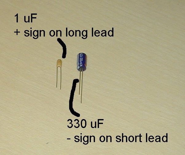
Polarized capacitors: As the instructions warn, the markings on these will vary from semester to semester. This semester, the 1uF capacitor is mustard-colored, and has a nearly-invisible "+" sign marking the positive lead. Also, this lead is longer. The 330uF capacitor has a light grey stripe, with a rectangle that's supposed to be a "-" sign, marking the negative side. This lead is shorter, as well.
Voltage regulator. This is really hard to distinguish from the transistor (step 7). Frankly, I can't read the lettering on this one at all!
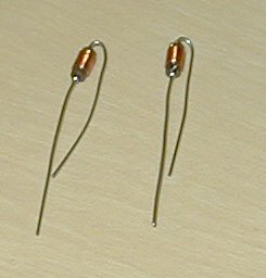
Inductors. Note how the leads are bent so it'll fit the holes in the board.
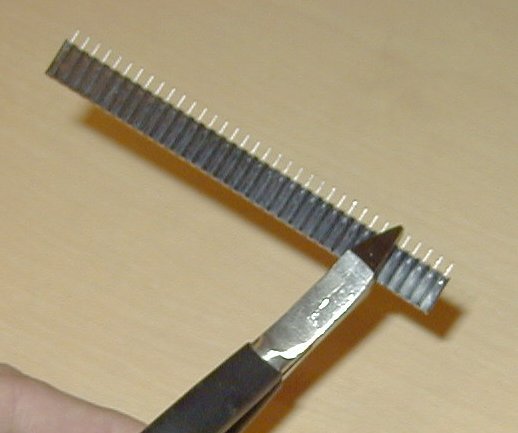
Female socket header. I've always had much better luck cutting it with the diagonal cutters than using either of the techniques in the lab manual.
RJ11 Connector. Oops, I don't have one here at home to take a picture...